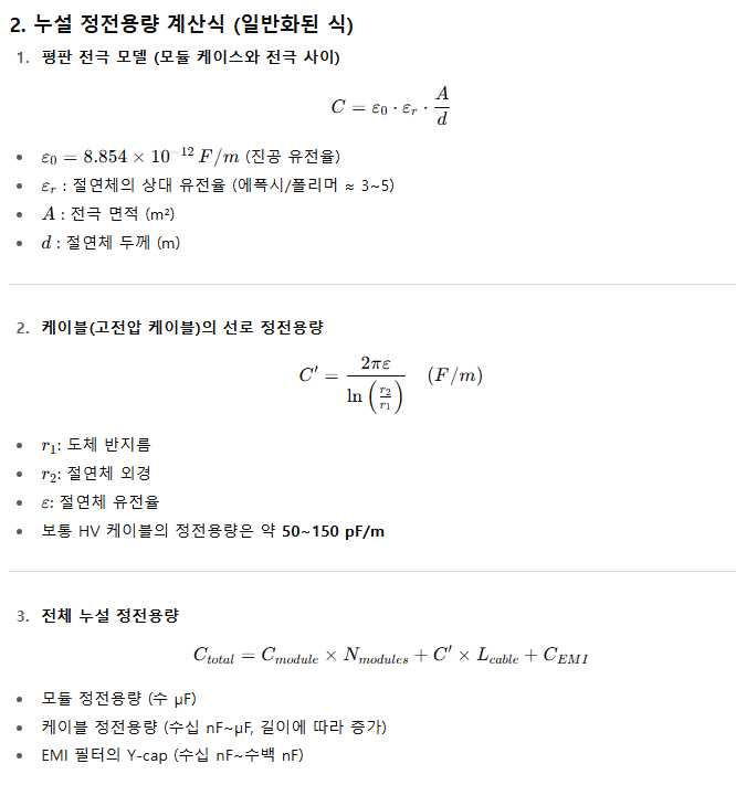
The total leakage capacitance of an ESS (Energy Storage System) is primarily calculated as the sum of the capacitances generated by the battery modules, cables, inverter, and cabinet structure . The sum of these capacitances is the leakage capacitance measured by the Insulation Monitoring Device (IMD).
Below is a table summarizing the leakage capacitance of each element based on a typical 1MWh-class ESS (DC 1000V system).
|
component |
Leakage capacitance range (approximately) |
explanation |
|
battery module |
0.5 ~ 2 µF/module |
Depends on the number of module cells and case insulation method |
|
Cable (DC Bus) |
20 ~ 60 nF/m |
Length and shielding structure influence, DC 100m → approx. 2~6 µF |
|
Inverter/PCS |
1 ~ 10 µF |
Parasitic capacitance due to EMI filter and DC-LINK capacitor |
|
Cabinet/Structure (GND) |
0.5 ~ 5 µF |
Electrostatic capacitance between metal case and ground, influence of panel area |
|
Others (sensors, communication lines) |
0.1 ~ 0.5 µF |
Parasitic capacitance of additional elements such as measurement lines and communication lines |
|
Total (1MWh class) |
5 ~ 50 µF |
There may be a ±20% deviation in actual measurements. |
That is, the total leakage capacitance of a 1MWh-class ESS is usually distributed in the range of 5 to 50 µF , and varies depending on the cable length, inverter capacity, and number of battery modules.
In ESS (voltage 1,000V, capacity 1,000Ah), **Leakage Capacitance (Ce)** is the parasitic capacitance that the battery cells, modules, cables, PCS, inverter, and wiring have with respect to the ground.
1. Causes of leakage capacitance
-
Between battery module/rack and metal case → Parasitic capacitance due to flat electrode structure
-
High voltage cable insulation and ground (GND) → line capacitance of the cable
-
PCS, inverter internal EMI filter → Y-Cap (Line-to-Ground Capacitor)
-
Cable length and layout → The longer the length, the greater the leakage capacitance.